Telecom Solution
Telecom Cable Tie Solutions for Base Stations, Towers and Network Cabinets
Weather-resistant cable tie and fixing solutions for telecom towers, rooftop base stations, outdoor cabinets, fiber routes, coax feeder cables, and repeated maintenance access.
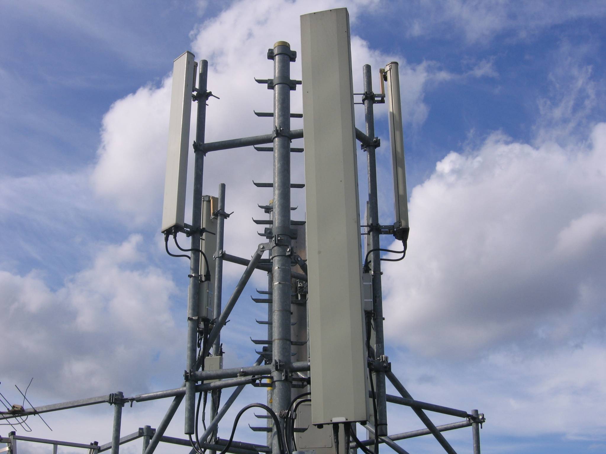
Real rooftop base station photo used for industry context. Photo: ~Pyb, CC BY-SA 3.0, Wikimedia Commons.
Procurement Snapshot
Best Fit Buyers
Telecom contractors, tower companies, outdoor cabinet builders, fiber network installers, and MRO distributors.
Main Decision Factors
UV resistance, vibration, cable jacket protection, corrosion risk, installation speed, and maintenance access.
Documents to Request
Material sheet, tensile data, UV/weathering statement, RoHS/REACH, and batch inspection report.
Common Order Format
Installer bags, project cartons, cabinet kits, private-label packs, or mixed telecom maintenance kits.
Industry Introduction
Telecom infrastructure depends on stable cable routing across towers, rooftop sites, outdoor cabinets, fiber distribution points, and equipment shelters. Cable ties hold coaxial feeders, fiber conduits, power cables, grounding wires, and service loops in safe positions.
Unlike indoor cable management, telecom fixing points face sunlight, rain, wind vibration, temperature cycling, corrosion, and repeated service visits. Poor cable retention can create sagging, jacket wear, signal service risk, and avoidable maintenance work.
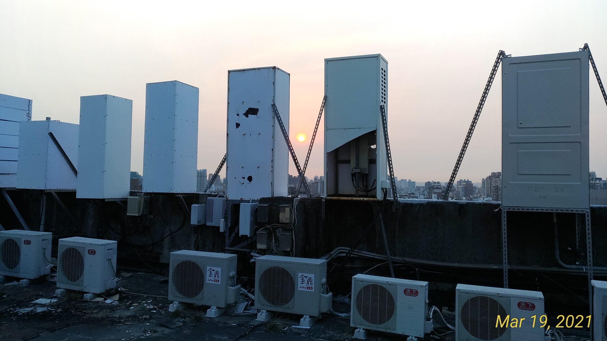
Real rooftop telecom cabinet photo. Photo: Jidanni, CC BY-SA 4.0, Wikimedia Commons.
Industry Pain Points
UV Aging
Indoor-grade ties can crack and lose strength after long sun exposure.
Cable Wear
Loose feeders can rub against brackets, rails, or cabinet edges.
Corrosion Risk
Coastal and rooftop sites may require stainless steel or corrosion-resistant fixing.
Maintenance Access
Technicians need organized routing that can be inspected and serviced quickly.
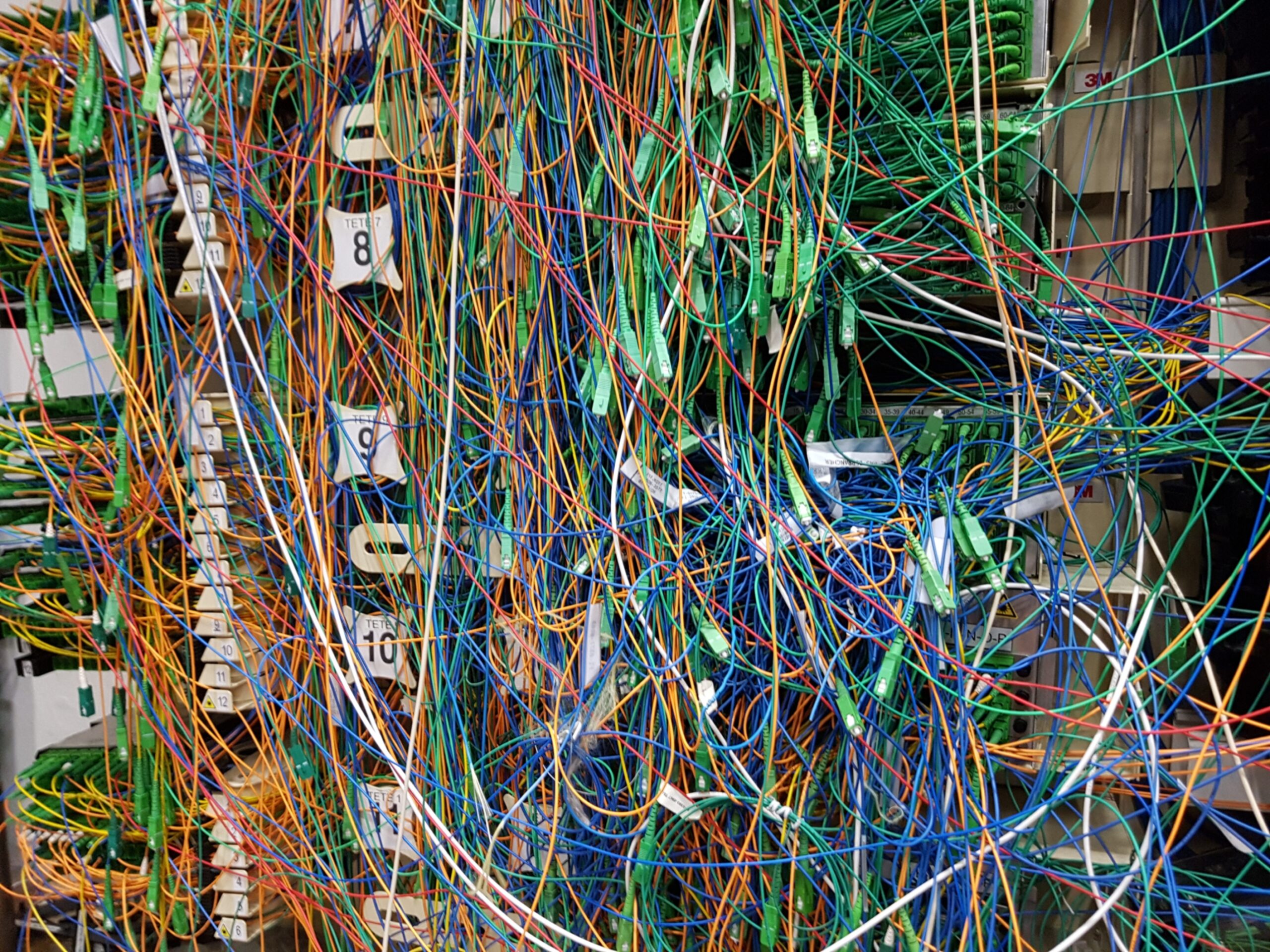
Real fibre distribution problem photo used to illustrate cable routing and maintenance risk. Photo: InfosReseaux, CC BY 4.0, Wikimedia Commons.
On-Site Problem Analysis
Telecom cable tie failures usually come from exposure mismatch and unmanaged routing. A tie that works in a cabinet may not survive tower vibration, rooftop heat, or coastal salt spray.
- Tower feeders: need UV resistance, vibration retention, and strong mounting intervals.
- Outdoor cabinets: need tidy routing, service loops, and separation of fiber and power cables.
- Rooftop sites: need weather resistance and protection from cable movement.
- Maintenance risk: disorganized cable routes increase service time and make faults harder to trace.
Solution Selector
Use this table to convert telecom site problems into a practical product starting point.
| Field Problem | Recommended Choice | When to Use |
|---|---|---|
| Tower feeder UV exposure | CT-TEL-UV-HD heavy-duty UV tie | Outdoor tower, rooftop, and exposed cable support points. |
| Cabinet fiber organization | CT-TEL-REL releasable tie and mounts | Serviceable cabinets and fiber/power separation. |
| Coastal or high-corrosion site | CT-TEL-SS316 stainless steel tie | Coastal rooftops, exposed brackets, and long-life severe environments. |
Recommended Solution
Use UV-resistant nylon ties for ordinary outdoor routing, releasable ties for service cabinets, mounts and clips for controlled spacing, and stainless steel ties for severe outdoor or coastal sites.
Base Station Cables
UV-resistant heavy-duty ties for feeder and fiber conduit support.
Outdoor Cabinets
Releasable ties and mounts for neat serviceable cable grouping.
Rooftop Sites
Weather-resistant ties and clips for exposed routes and wind movement.
Coastal Sites
316 stainless steel ties for corrosion and severe outdoor exposure.
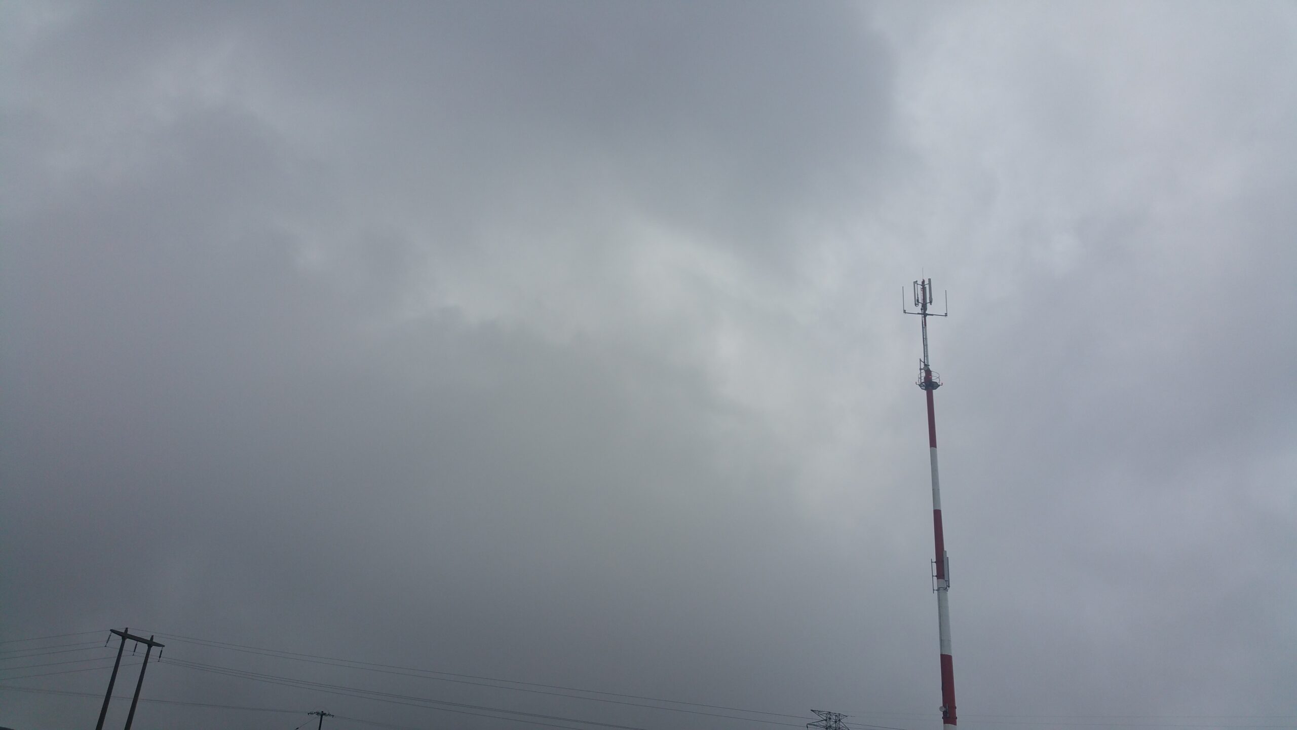
Real cellular base station photo for tower-route context. Photo: Deavmi, CC BY-SA 4.0, Wikimedia Commons.
Product Combination
Product images below are used for product identification and material selection. Demonstration images are not presented as telecom field installation or customer case photos.
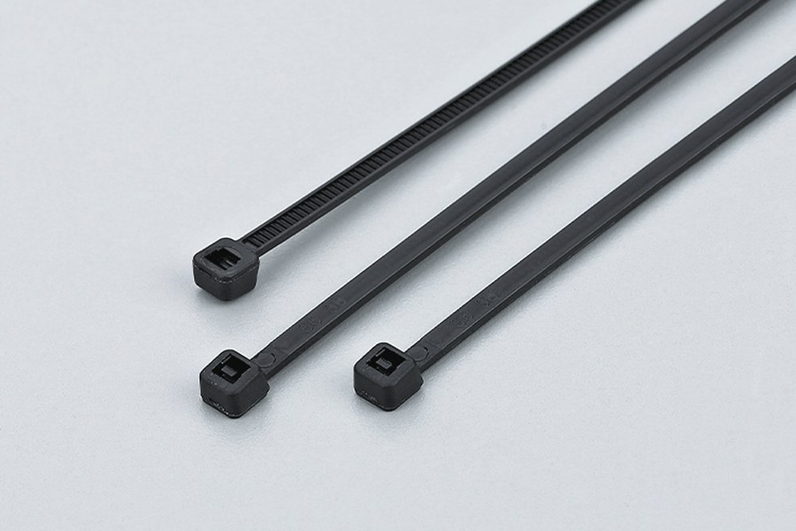
UV-resistant black nylon ties for outdoor feeder, rooftop, and general cable routing.
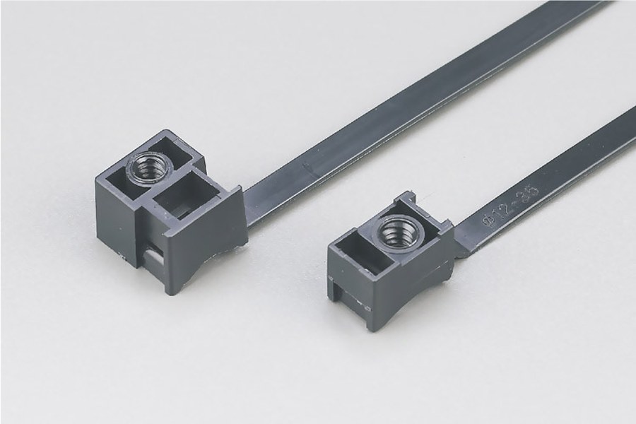
Screw-mount tie designs for cabinet rails, brackets, and controlled fixing points.
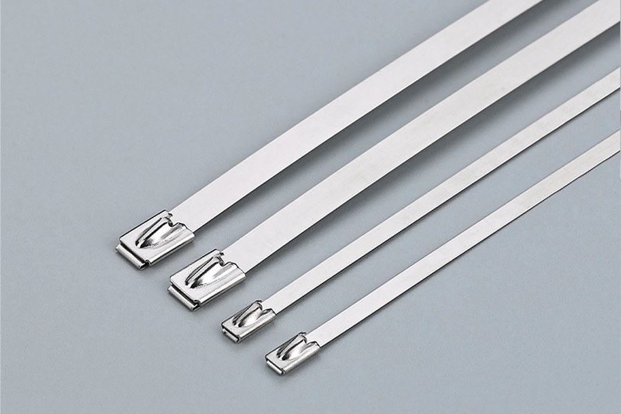
Stainless steel ties for coastal rooftops, exposed brackets, and corrosion-prone sites.
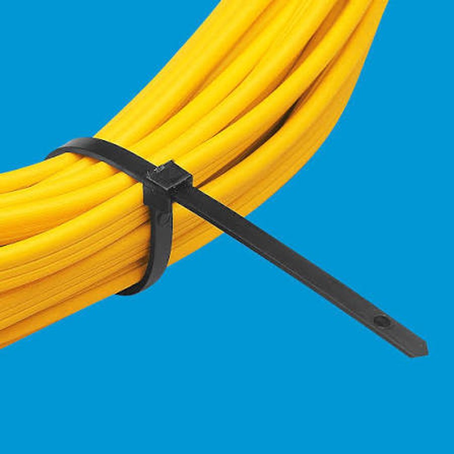
Product demonstration: one black nylon tie fully wraps the cable bundle and exits the locking head correctly.
| Application Zone | Recommended Products | Purpose |
|---|---|---|
| Tower feeders | UV-resistant heavy-duty cable ties | Hold coax and fiber conduits on exposed tower routes |
| Outdoor cabinet | Releasable ties, mounts, cable clips | Organized service access and cable separation |
| Rooftop routes | UV cable ties, stainless steel options | Weather and wind-resistant cable retention |
| Coastal site | 316 stainless steel cable ties | Corrosion-resistant severe-duty fixing |
Product Parameters
| Product Type | Material / Design | Performance Focus | Typical Use |
|---|---|---|---|
| UV-resistant tie | UV-stabilized nylon | Outdoor sunlight resistance | Tower and rooftop cable support |
| Releasable telecom tie | Releasable nylon design | Maintenance access | Cabinets and service loops |
| Cable mount / clip | PA / adhesive / screw mount options | Controlled spacing | Cabinet, rail, and bracket fixing |
| Stainless steel tie | 304 / 316 stainless steel | Corrosion and severe weather | Coastal or exposed telecom routes |
Recommended SKU Set
| Suggested SKU | Product Role | Typical Spec Direction | Recommended Use |
|---|---|---|---|
| CT-TEL-UV-HD | Outdoor feeder tie | UV-resistant heavy-duty nylon | Base station tower and rooftop cable routes |
| CT-TEL-REL | Serviceable tie | Releasable nylon tie | Cabinet maintenance and service loops |
| CT-TEL-MOUNT | Cable mount | Screw mount / adhesive mount / clip option | Controlled routing inside cabinets or along rails |
| CT-TEL-SS316 | Severe-duty tie | 316 stainless steel | Coastal, exposed, or high-corrosion telecom sites |
Installation Steps
The installation flow below is kept as a checklist because no verified telecom field installation photo is available for this page. The two images are product demonstrations used to show correct fixing geometry, not field case photos.
- Map the cable route: identify tower, rooftop, cabinet, and equipment entry paths.
- Select outdoor grade: match UV, corrosion, vibration, and maintenance needs.
- Set support spacing: prevent sagging and cable movement in wind.
- Protect cable jackets: avoid over-tightening and sharp bracket contact.
- Separate cable groups: keep fiber, power, feeder, and grounding routes serviceable.
- Inspect after installation: check tail trimming, tie head position, and future access.
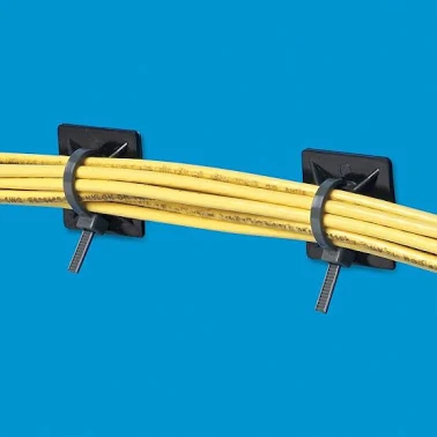
Product demonstration: mount-backed ties keep spacing controlled and prevent cable drift. Not a customer field photo.
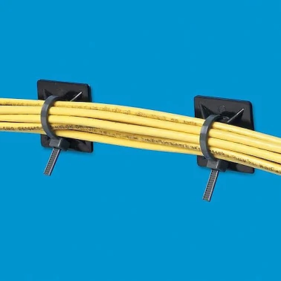
Product demonstration: the tie forms a closed loop around the cable bundle, with the tail exiting one locking head.
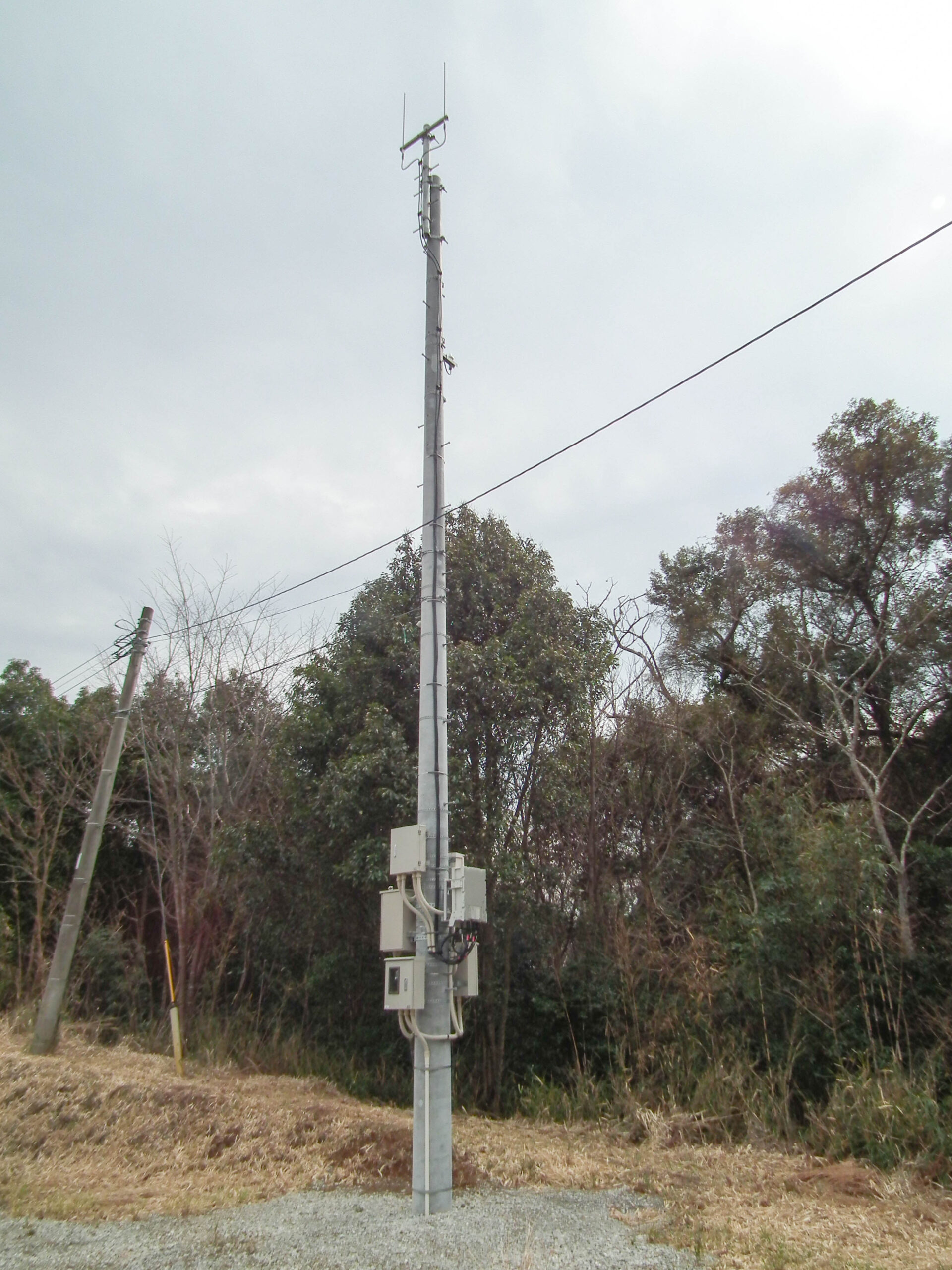
Real base station equipment photo used for field-context reference. Photo: Jade stern 2008, CC BY-SA 3.0, Wikimedia Commons.
Field Case
Improving Cable Retention on an Outdoor Base Station
Application: Outdoor base station feeder and fiber cable management.
Problem: Standard cable ties cracked after outdoor exposure, causing loose cable sections and extra maintenance inspection.
Solution: CableTiesMFG recommended UV-resistant heavy-duty ties for exposed routes, releasable ties in cabinets, and 316 stainless steel ties for high-exposure brackets.
Result: The site improved cable retention, reduced loose-cable checks, and made future maintenance routing clearer.
Why Choose CableTiesMFG
Telecom Options
UV ties, releasable ties, mounts, clips, and stainless steel cable ties.
Site Support
Recommendations by tower, rooftop, cabinet, coastal, and maintenance conditions.
Quality Documents
Material sheets, tensile data, RoHS/REACH, and batch inspection support.
One-Stop Supply
Cable ties, mounts, heat shrink, cable glands, and installation accessories.
Quality & Documentation
- Material data sheet
- Tensile test record
- UV/weathering statement
- RoHS / REACH statement
- Batch inspection report
FAQ
What cable ties are best for telecom towers?
UV-resistant heavy-duty nylon ties are suitable for ordinary exposed routes. Stainless steel ties are recommended for severe, coastal, or high-corrosion conditions.
Should telecom cabinets use releasable ties?
Releasable ties are useful where technicians need maintenance access, service loops, or future cable changes.
How do I prevent cable jacket wear?
Use correct tie spacing, avoid sharp bracket contact, control tension, and use mounts or clips where the cable route changes direction.
Do you supply telecom cable tie kits?
Yes. CableTiesMFG can recommend telecom kits by site type, cable diameter, environment, and order quantity.
RFQ Information Needed
Site Conditions
Tower, rooftop, cabinet, indoor shelter, coastal exposure, UV level, and expected service life.
Cable Route
Cable diameter, bundle weight, spacing, rail profile, cabinet layout, and whether mounts are required.
Commercial Details
Quantity, sample needs, packing preference, delivery schedule, and compliance documents.
Image Sources
Real telecom scene photos on this page are used as industry context from Wikimedia Commons. Product and demonstration photos are CableTiesMFG media assets used for product identification and fixing-geometry explanation. Demonstration photos are not presented as telecom field installation or customer case photos.
- Rooftop GSM base station: ~Pyb, CC BY-SA 3.0.
- Telecom rooftop cabinets: Jidanni, CC BY-SA 4.0.
- Cellular base station tower: Deavmi, CC BY-SA 4.0.
- Fibre distribution problem: InfosReseaux, CC BY 4.0.
- WiMAX base station equipment: Jade stern 2008, CC BY-SA 3.0.
- Product photos: CableTiesMFG media assets for UV nylon ties, screw-mount ties, stainless steel ties, cable tie mounts, and cable-bundle demonstration.


Contact Us
Send us your telecom site type, cable diameter, exposure environment, tie spacing, and expected quantity. Our team will recommend the right telecom cable tie combination.